York HVAC & ICP Heat Pump Wiring: The Expert’s Breakdown! Icp heat pump part # 1172465
Heat pumps are essential components of modern HVAC systems, providing both heating and cooling for residential and commercial properties. Understanding their functionality and maintenance is crucial for ensuring optimal performance and longevity. This involves familiarizing oneself with key components and troubleshooting potential issues.
Heat Pump Defrost Control Board Panel

The defrost control board is a critical element within the heat pump system. Its primary function is to monitor the outdoor coil temperature and initiate the defrost cycle when necessary. During colder months, frost can accumulate on the outdoor coil, reducing its efficiency and hindering its ability to extract heat from the outside air. The defrost control board utilizes sensors to detect this frost buildup. Once the board determines that a certain threshold of frost has accumulated, it activates the defrost cycle. This process involves temporarily reversing the flow of refrigerant, effectively turning the outdoor coil into a condenser. This allows hot refrigerant gas to flow through the coil, melting the accumulated frost. The defrost cycle is typically short, lasting only a few minutes, to minimize the disruption to the heating process inside the building. Different heat pump models may employ varying defrost control board designs and algorithms. Some boards utilize a time-temperature defrost control, which initiates a defrost cycle based on a pre-determined time interval and outdoor temperature. Others utilize a demand defrost control, which relies more heavily on sensor data to determine when a defrost cycle is truly needed, potentially leading to more efficient operation. Replacing a faulty defrost control board is a relatively common repair. It is important to select a replacement board that is compatible with the specific heat pump model to ensure proper operation and avoid further damage to the system. Identifying the correct board often involves referencing the manufacturer's specifications or consulting with a qualified HVAC technician. When replacing the board, it is crucial to disconnect the power to the heat pump and to carefully label all wires before disconnecting them from the old board. This will help ensure that the wires are reconnected correctly to the new board.
Understanding Heat Pump Wiring Diagrams

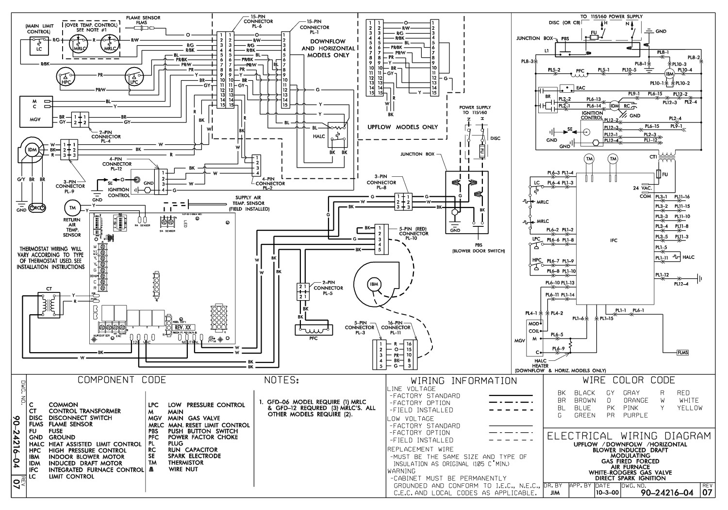
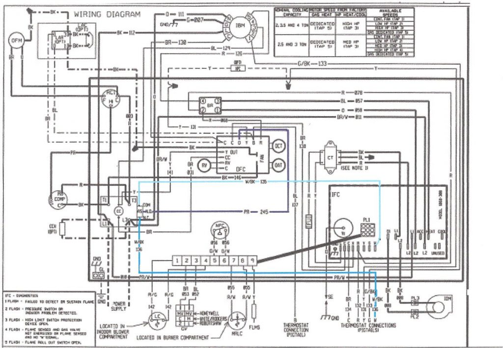
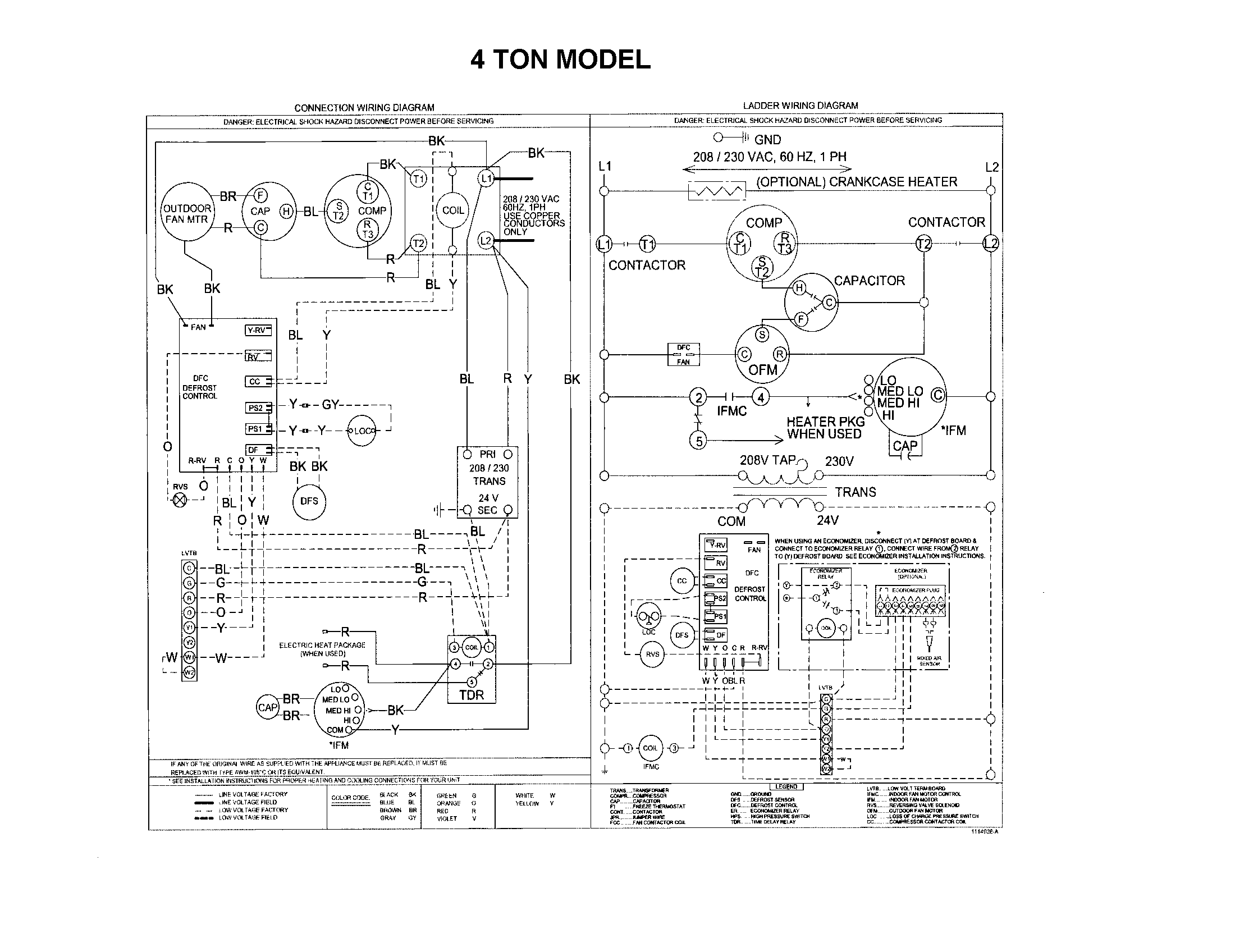
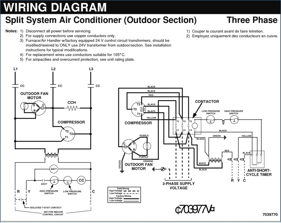
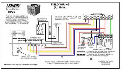
Heat pump wiring diagrams serve as essential blueprints for understanding the intricate electrical connections within the system. These diagrams provide a visual representation of how various components, such as the compressor, fan motors, reversing valve, and control board, are interconnected. Analyzing these diagrams is crucial for troubleshooting electrical issues, performing repairs, and ensuring safe and efficient operation. A typical heat pump wiring diagram includes symbols representing each component and lines indicating the wiring connections between them. The diagram also provides information on the voltage, amperage, and wire gauge requirements for each circuit. Understanding the color codes used in the diagram is essential for identifying the correct wires. For example, red wires typically indicate power, black wires indicate neutral, and green or bare wires indicate ground. Tracing the wiring connections in the diagram can help to identify potential problems, such as short circuits, open circuits, or loose connections. By using a multimeter to test the voltage and continuity of the wires, technicians can pinpoint the exact location of the fault. Different heat pump models have different wiring configurations. Therefore, it is essential to consult the correct wiring diagram for the specific model being worked on. These diagrams are typically available from the manufacturer or online resources. In addition to helping with troubleshooting, wiring diagrams are also helpful for installing new components or modifying the existing wiring. It is crucial to follow the diagram precisely to avoid creating electrical hazards or damaging the system. Working with electrical systems can be dangerous, so it is always recommended to consult with a qualified electrician or HVAC technician if you are not comfortable working with electricity.
If you are searching about [DIAGRAM] Icp Heat Pump Defrost Board Wiring Diagram For Model For you've visit to the right web. We have 25 Pictures about [DIAGRAM] Icp Heat Pump Defrost Board Wiring Diagram For Model For like Wiring diagram for ICP heat pump, Goodman Heat Pump Wiring Diagram and also Wiring diagram for ICP heat pump. Here it is:
[DIAGRAM] Icp Heat Pump Defrost Board Wiring Diagram For Model For
![[DIAGRAM] Icp Heat Pump Defrost Board Wiring Diagram For Model For](https://i151.photobucket.com/albums/s160/Houston204/GoodmanGSH13_zpsdad42c36.jpg) mydiagram.online
mydiagram.online Icp Heat Pump Thermostat Wiring Diagram
 wireenginedenaturize.z14.web.core.windows.net
 ICP Heat Pump Part # 1172465 - Dual Run Capacitor - Genuine OEM Part
 vacuumssupply.com
 York Heat Pump Wiring Schematic
 circuitlibgromets.z13.web.core.windows.net
 Icp Hvac Wiring Diagrams
 guidefixmoore.z13.web.core.windows.net
 Heat Pump Wiring Diagram View - Wiring Diagrams Thumbs - Heat Pump
 2020cadillac.com
 wiring diagram ruud rheem diagrams thermostat furnace fuel justanswer hvac emergency
York Heat Pump Compatible Thermostat Wiring Diagram - Collection
 faceitsalon.com
 communicating diagram pump heat wiring thermostat compatible york hvac non vs trane system collection circuit located where source
Icp Wiring Diagrams
 wiringmanualprettiness.z14.web.core.windows.net
 Icp Hvac Wiring
 circuitenginebushed.z13.web.core.windows.net
 [DIAGRAM] Wiring Diagram For York Heat Pump - MYDIAGRAM.ONLINE
![[DIAGRAM] Wiring Diagram For York Heat Pump - MYDIAGRAM.ONLINE](https://lh3.googleusercontent.com/blogger_img_proxy/AEn0k_ttrGFIzPmshb9tCzEXE1axp-vY-EwVlo3-qLC7NKZeGU07j969eShzev1I00rWbbrdy1yxl7FttQd2uhEfBbQlPHTdjeotzCYjZWz6jKH_EqsynpIhSUuWaXlbZrPDLTs=s0-d) mydiagram.online
mydiagram.online Warren Hvac Heat Pump Wiring Diagram
 manualgladjanusflo.z14.web.core.windows.net
 [DIAGRAM] Wiring Diagram For York Heat Pump - MYDIAGRAM.ONLINE
![[DIAGRAM] Wiring Diagram For York Heat Pump - MYDIAGRAM.ONLINE](https://c.searspartsdirect.com/lis_png/PLDM/10059194-00003.png) mydiagram.online
mydiagram.online Goodman Heat Pump Wiring Diagram And Installation Guide
 schempro.com
 [DIAGRAM] Old Icp Furnace Wiring Diagram - WIRINGSCHEMA.COM
![[DIAGRAM] Old Icp Furnace Wiring Diagram - WIRINGSCHEMA.COM](https://lh3.googleusercontent.com/blogger_img_proxy/AEn0k_u8GQTs035nfgU84hCHFsiFu-BXchWEHQTQoizvNbodXY12V8qxRonGB_iOOeU_y8I0xHTTuZYWl2oCs1ru3aLlQ-XBhME8x9HeM_p-AP99GzAzxRNU7tWYSQvp4CpykWs=s0-d) wiringschema.com
wiringschema.com I Have A ICP Heat Pump 2 1/2 Ton With With Electric Heat. Mdl No
 www.justanswer.com
 [DIAGRAM] Wiring Diagram For York Heat Pump - WIRINGSCHEMA.COM
![[DIAGRAM] Wiring Diagram For York Heat Pump - WIRINGSCHEMA.COM](https://lh3.googleusercontent.com/blogger_img_proxy/AEn0k_viWM8Og2yiEdzKWR6my9N2E1XpGZtB29wvo9wrdm5GJK7nJdeZ4KAIBC_uuCAMxJCwXNG19MPQirzM7mIP8II_4c8n5lH0QN0HZOYLghUuG7lzBgJ3LZgfh0wIwseScU0=s0-d) wiringschema.com
wiringschema.com Heat Pump Defrost Control Board Panel Replaces ICP Heil Tempstar
www.northamericahvac.com heil tempstar icp defrost comfortmaker
Uncovering The Intricacies Of Heat Pump Wiring Diagrams
circuitblaze.com Rheem Heat Pump Wiring Color Code
 wiringmanualreiterance.z21.web.core.windows.net
 Wiring Diagram For ICP Heat Pump
 diagramio.com
 Goodman Heat Pump Wiring Diagram
 www.tankbig.com
 pump heat goodman wiring diagram wire
York Hvac Wiring Diagrams
 fity.club
 [DIAGRAM] Heat York Diagram N Wiring Pump Ahc1606a - MYDIAGRAM.ONLINE
![[DIAGRAM] Heat York Diagram N Wiring Pump Ahc1606a - MYDIAGRAM.ONLINE](https://s1.manualzz.com/store/data/000838406_1-f289d9f3f2d8ee9796051f971ff1325f.png) mydiagram.online
mydiagram.online How To Read And Understand A Goodman HVAC Wiring Diagram
 design1systems.com
 ICP 4 Ton Heat Pump Package Unit 208/230V 1-phase – HVAC Deal
 hvacdeal.com
 Uncovering the intricacies of heat pump wiring diagrams. Icp hvac wiring diagrams. Icp 4 ton heat pump package unit 208/230v 1-phase – hvac deal